
Photoelectric effect
Experiment
As physicist between 19th and 20th centuries, we will experimentally investigate dependence of stopping voltage (or max. kinetic energy of electrons in electronvolts) U0(f) on frequency of incident light on photocatode.
We will experience graphical processing of data (e.g. in MS Excel), which will provide posibility to verify Einstein equation and calculate Planck constant and material charakteristics (work function).
Outer photoelectric effect can be investigated using two methods:
- Method of charging capacitance on stopping voltage – simplier method.
Czech remote laboratory – Outer photoeffect (C)
German remote laboratory
- Study of volt-amperove characteristics of vacuum phototube – more complex method, suitable for university stundets and students of technical subjects.
Czech remote laboratory – Outer photoeffect
http://kdt-29.karlov.mff.cuni.cz
PC simulation (can help with understanding nature of experiment).
- This text, other sources of theory.
- Simulation.
- Remote experiment
Description – view from above
")
- Light source
(1a – 125 W mercury lamp; 1b – lamp shield) -
Narow-band interference filters for monochromatic light selection
(2a – ThorsLab filter-wheel shield; 2b – carusel with filters except the fully-shielded position 0; 2c – High-luminance infra-red LED 940 nm with wide angle of emission) -
Phywe vacuum phototube
(3a – side shield; 3b – cover; 3c – internal phototube shield with two windows; 3d – anode shield between both windows for incoming light; 3e – anode at symmetry axis of the photocathode; 3f – photocathode) - Light reflecting mirror for the webcam
- Webcam (NOTE: The webcam is sensitive for light out of the visible range and misrepresents true colours!)
Method A: Method of charging capacitance on stopping voltage
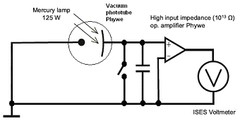
To study properties of outer photoelectric effect we use vacuum phototube, which consists of two electrodes in glass flask, from where the air was exhausted. The light (electromagneti radiation) falls on bigger electrode (photocatode), its frequency f is related to its wavelength λ
| f = c/λ , | (2) |
|
| Fig. 2: Diagram of vacuum phototube, with parallelly connected capacitor and switch for discharge. Photocatode is connected to positive input of operational amplifier, anode to negative input. |
The voltage on capacitor can't raise to infinity when charging; increasing negative elektric charge on anode repulses released electrons from photocatode more and more, so electrons can't move to anode at certain voltage and the capacitor can't charge more. This negative value of voltage is called stopping voltage U0 (because it stops and repulses next incoming electrons) and it is measurable with special voltmeter with amplifier. We can also experimentally investigate, how value of stopping voltage depends on wavelength, resp. on frequency f of light falling on photocatode ... U0(f).
The source of light is mercury lamp with power 125 W. It provides spectral light with determined wavelengths 365 nm, 405 nm, 435 nm, 536 nm a 578 nm, which can be chosen thanks to interference filters F1 - F5. Filter F6 responds to dark phototube, it allows to emit light from infrared LED diode at wavelength 940 nm.
Method B: Study of the volt-ampere characteristics of a vacuum phototube
When studying the volt-ampere characteristics of a vacuum phototube, the phototube is a part of simple circuit in the figure 5 together with a voltage source and a resistor around 50 megaohms. (The higher resistance, the higher amplification of the photocurrent.) The resistor is connected between the photocathode and the ground (GND). The measurement can be controlled by the user, or the experiment platform ISES provides an automatic scan (using a saw signal at the voltage output).
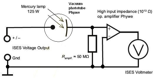
Fig. 5: Scheme of the electrical circuit.
The voltage on the amplification-resistor is measured by the Phywe high input impedance amplifier (1013 Ω), connected to the module Voltmeter.
Simple cut-off filters at the analog input channels are used for smoothing the signal and for reduction of aliasing. High-quality relays are used for the selection of the amplification-resistor 10–100 megaohms.
A 6-position motorized filter wheel is used for the selection of the wavelength of incident light. Well known wavelengths are due to the usage of high-quality interference filters and a mercury lamp providing five bright spectral lines at 365 nm, 405 nm, 436 nm, 546 nm, and 567 nm.
The mercury lamp (125 W) has a luminophore to reduce the effect of aliasing.
For more details please read User's Manual.