
Difraction on microobjects
Physical Background
Diffraction, which arises in closeness of obstacle when light passes from point source, was investigated by Fresnel. In this phenomenon, which is called Fresnel’s diffraction, we face the problem of interference of spherical waves, based on Huygens principle. If we consider diffraction from distant source (monochromatic coherrent light), wavefront is nearly flat. We approach to phenomenon, which arise by diffraction of parallel beams with planar wavefronts, which are called Fraunhofer’s diffraction.
If we are distant enough from the source, qualitative and quantitative analysis is explained by Fraunhofer's diffraction – in our case one-dimensional slit. Slit AC with width d is illuminated by perpendiculary falling monochromatic light (one coulour light, that is light consisting of only one wavelength) is in every point in whole its width source of elementary waves (simiarly as interface between two medium by refraction and reflection). From every point there is propagated spherical wave. Since beams come out in all directions, they interfere, and light behind the slit is not propagated uniformly in all directions, as shown in the experimental observation.
We choose paralell bunch of beams that come out of the slit under the angle α (diversion of original way of beams before falling on the slit, see fig. 1).
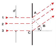
Figure 1 The Fraunhofer’s diffraction phenomenon on a slit.
In planar wavefront AB, which is perpendicular to the direction of propagation, individual bunches have different phase, which depends on travelled distance. If e.g. δ is the delay of edge beam CB to second edge beam in point A (beam 1), the delay of beam, which comes through the middle of the slit (that is axial beam) is δ/2. Phase difference of all other beams raises with increasing distance of beam from point A to point C. Then to every beam p (which is located between beams 1 and 2) we find between beams 2 and 3 such beam p´, which is distant half with of the slit and his phase difference is δ/2. From that we conclude, that every beam will destructively interfere, its delay is equal of unpaired numer of halves, so if the deviation of beams is such that δ equals paired number of halves, that is integer multiple of waves, which is expressed in following equation:
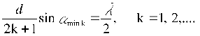
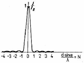
Figure 2 The distribution of the light intensity behind the slit and the condition for the location of minima
To explain the diffraction phenomenon, we will use Fraunhofer´s theory. This theory assumes, that a wave that falls on a slit is planar (Fig. 1). Diffraction phenomena of this type are called Fraunhofer´s diffraction and we will explain it on the basis of the elementary concepts in Fig. 1 and Fig. 2.
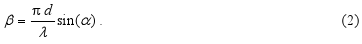
We assume that a planar monochromatic and coherent wave falls on the single slit of the width d = |AC|, and diffracts at an angle α, defining randomly chosen direction (see Fig.1). If the distance |BC| is just equal to the wavelength λ, then the sum of intensities of electric field from all the rays (of electromagnetic radiation ) that emerge from the slit in this direction is zero, or all these rays cancel in this direction. It may be proven by a simple logic: to every ray falling in the interval between the rays 1 and 2 corresponds only one ray from the other half of the slit, 2 and 3, which . mutually differ from each other a difference λ/2, and so they cancel each other Therefore, if we consider that a relation |BC| = d.sin α is valid and admit also another nonzero integer multiple of wavelength λ, we get a condition for the location of all minimum values ( see Fig. 2). The exact derivation of the diffraction pattern (which is not needed for a student ) derived by Fraunhofer, gives the detailed distribution of the intensity with the main maximum and number of other maxima and minima ( Fig . 2 ). This intensity can be expressed as a function of an angle α
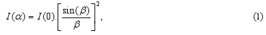
-
The location of minima of intensity (i.e. I(α) / I(0) = 0 ) in directions where it is
or the condition for the angles αmin,


-
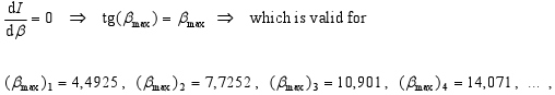
The location of maxima of intensity (i.e. I(α)/I(0) = max.) is then in points, where it is
or the condition for angles αmax
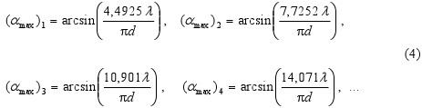
-
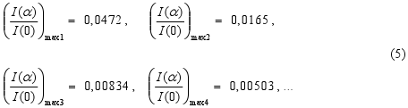
The relative magnitude of maxima of intensity (i.e. I(α) / I(0) ) in points where it is
Author of study text: Prof. Dr. František Schauer, Univerzita Tomáše Bati ve Zlíně