
Heisenberg uncertainty principle (out of service until 1 March 2024)
Experiment
As a source of the monochromatic and coherent radiation we will use two lasers with a wavelength λ1 = (632 ± 10) nm and λ2 = (532 ± 10) nm. Their radiation falls on the screen with the slit. The diffraction pattern intensity distribution behind the slit is measured by the semiconductor photodiode situated at a distance a from the slit a = (2152 ± 1) mm (see Fig. 3) and using the V-meter modules of the system ISES. The photodiode is attached to the XY plotter enabling the recording of the diffraction pattern. The schematic arrangement of the diffraction experiment for the proving (disapproving) the Heisenberg uncertainty principle is in the Fig. 3.
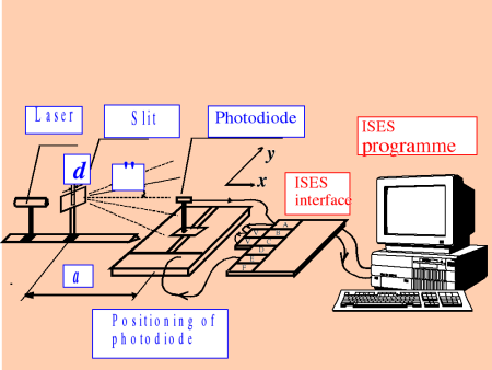
Figure 3 The schematic arrangement of the remote experiment Heisenberg uncertainty principle, recorded by the ISES system and transmitted by Internet

Figure 4 An example of the distribution of light intensity while bending phenomenon on the slit present; measurements used: laser of λ1 = 628,10 nm (d = 180 μm), red curve is the fitting by the optimalisation program (Origin 7.5)